Yagi antennas are very directional antennas that offer very high gains compared to most other antennas.
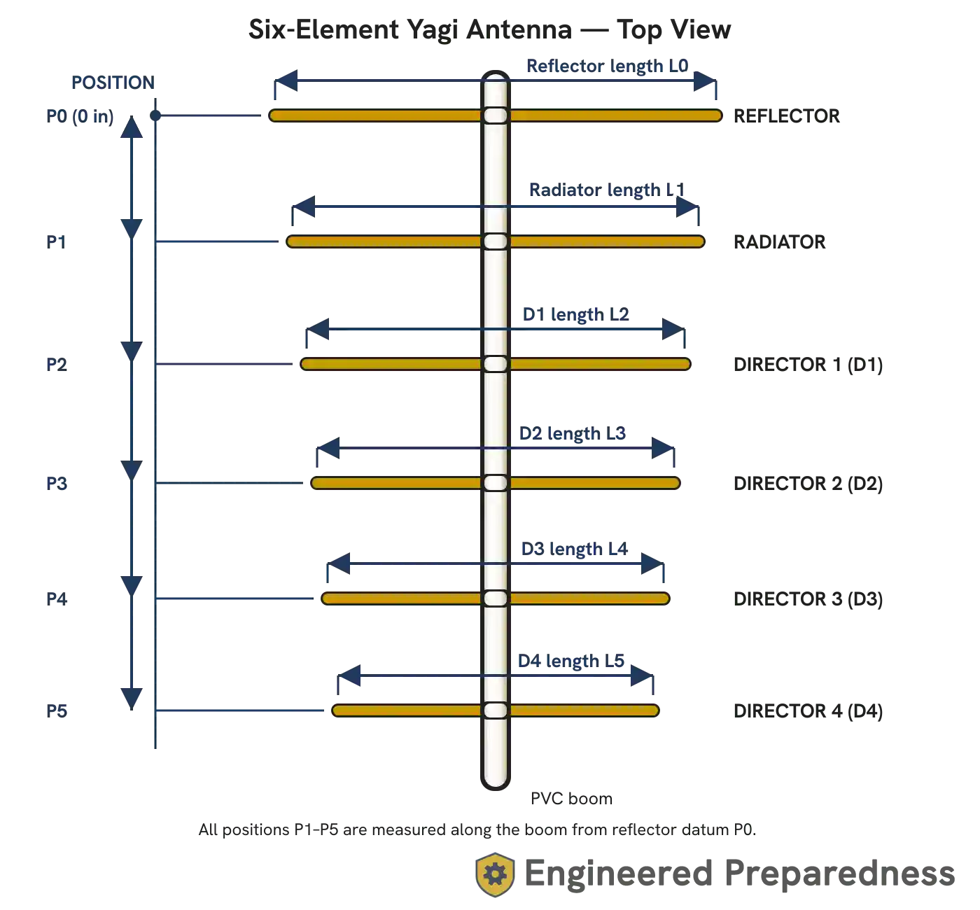
Yagi antennas are very directional antennas that offer very high gains compared to most other antennas. The elements should all be conductive materials, and the boom is a non-conductive material that simply holds everything in position. The radiation is along the boom’s axis and radiates down as shown in the diagram.
The top-most element shown is the reflector — this is what makes the antenna directional, as it reflects the signal in one direction.
The next element down is the radiator, which is essentially a dipole.
The remaining elements up are called directors, and the larger the number of them, the higher the gain of the antenna. They “steer” the signal into a narrow “beam”, making it more powerful in that one direction (and also improving the sensitivity for reception in that same direction).
| No of Directors | Approx. Gain (dB) |
|---|---|
| 1 | 6.4 |
| 2 | 7.6 |
| 3 | 8.6 |
| 4 | 9.3 |
| 5 | 10.0 |
| 6 | 10.5 |
| 7 | 11.0 |
| 8 | 11.4 |
| 9 | 11.8 |
| 10 | 12.1 |
| 11 | 12.5 |
| 12 | 12.8 |
| 13 | 13.0 |
| Element | Length Formula | Position Formula |
|---|---|---|
| Reflector | L0 = 5972 / F | P0 = 0 |
| Radiator | L1 = 5689 / F | P1 = 2832 / F |
| Director 1 | L2 = 5367 / F | P2 = 885 / F |
| Director 2 | L3 = 5316 / F | P3 = 2125 / F |
| Director 3 | L4 = 5269 / F | P4 = 2538 / F |
| Director 4 | L5 = 5226 / F | P5 = 2951 / F |
| Director 5 | L6 = 5188 / F | P6 = 3305 / F |
| Director 6 | L7 = 5152 / F | P7 = 3541 / F |
| Director 7 | L8 = 5121 / F | P8 = 3718 / F |
| Director 8 | L9 = 5092 / F | P9 = 3895 / F |
| Director 9 | L10 = 5067 / F | P10 = 4072 / F |
| Director 10 | L11 = 5044 / F | P11 = 4249 / F |
| Director 11 | L12 = 5024 / F | P12 = 4426 / F |
| Director 12 | L13 = 5006 / F | P13 = 4544 / F |
| Director 13 | L14 = 4991 / F | P14 = 4603 / F |
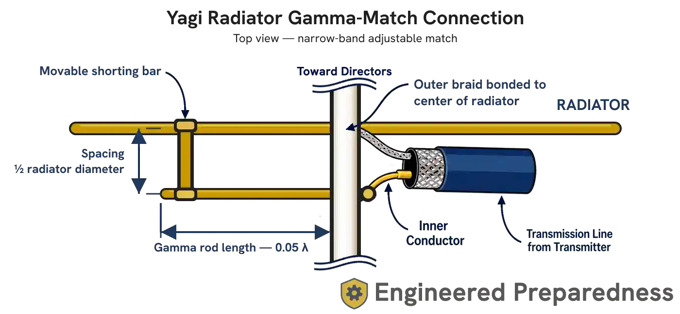
Unfortunately, Yagi antennas don’t naturally have a 50Ω impedance that we need to get a good SWR (they’re normally about 73Ω). While this can be fixed using a small matching transformer (BALUN), it’s normally accomplished using what’s called a “gamma match”. In this, the radiator is constructed out of a single piece of material instead of being split like a normal dipole would be. Then, the connection is made using a “tuning stub” that is adjusted to obtain the proper impedance match.
Notes:
